M3: Parametric Paravent, final presentation + critique
presentation%20flyerETH1facade
The last phase of competition was dedicated to programming and¬Ýproducing the final structure. For the last two weeks the students¬Ýintensively worked on the realization of the proposed¬Ýstructures. Various construction and material tests were¬Ýnecessary to prove design ideas and methodologies.The initial designers operated as project leaders and were¬Ýresponsible for coordinating the rest of the team.¬ÝThe final output was consist of the built structure and presentation¬Ýexplained concept, code and production.¬ÝA proposal for the complete space had to be presented.¬ÝEach team had 15 min. Among others the structure was¬Ýjudged by the following criteria:¬Ýlightness, flexibility,¬Ýtransparency, visual permeability,¬Ýimpact on room and expected users,visual effect and design as a freestanding component,complexity of parametric program/ script,simplicity in production and assembly.
STUDENT WORKS
Agata Muszynska, Magda Osinka, Jorge Orozco, Hideaki Takenaga
A starting point for the design was a concept of producing a standard element destined for nonstandard assembly.
There were basically two main ways for continuing the project. The first was to develop the idea of a smart element and an unpredictable, „freehand” mounting of it. The second – to concentrate on the possibilities of drawing a set of hundred or 500 different elements based on the same set of connectors. Though the elements would be quite unique – connecting every single one to another one would be possible threw the standarized connectors. The final product – a wall, structure would be placed also in a layer of unpredictability.
Eventually we decided on the first path ‚Äì producing a standard smart component. As assigning a cut of 500 identical parts to the robot ‚Äì would mean not using the possibilities it offers, we started to search for another method to produce the elements.¬Ý We reasearched on casting methods: pouring¬Ý silicone,¬Ý epoxy-rasin or polyurethane foam into a robot carved MDF forms. Construction weight turned out to be a problem.
We analyzed also simple laser cutting – but the idea went dead very fast as the laser cutter is limited to rather small range of thin materials.
Eventually we decided on vacuuming a folie onto a CNC milled or KUKA curved prototype model. We had several materials at hand to explore. We started with a lot of failures with different heat reaction of different materials. Some got teared, some melted too fast, the other ones didn’t want to melt at all or very slowly. Some were just too thick to mount into ETH vacuuming machine and others were just ‚Äûugly‚Äù.
We tried different kinds of PVC, Hard and Sponged Polypropylene, Polyethylene, Polycarbonate and Acryl. Thicknesses: from 0,3 mm to 2mm.
Every material behaved differently. Some were easier to control and some harder. We started to analyze what made a thin material stronger. The more bends or curves acctually the design had – the more rigid it was. After some experiments – we decided on introducing several ribs into the design.
The next issue was to optimize the connections. We started to explore press – stud joints to¬Ý vacuum them within the designed element. We tried several settings for connector location. We wanted to choose an option allowing for several different assembly angles ‚Äì to make the structure more dipendent on the user assembling it.
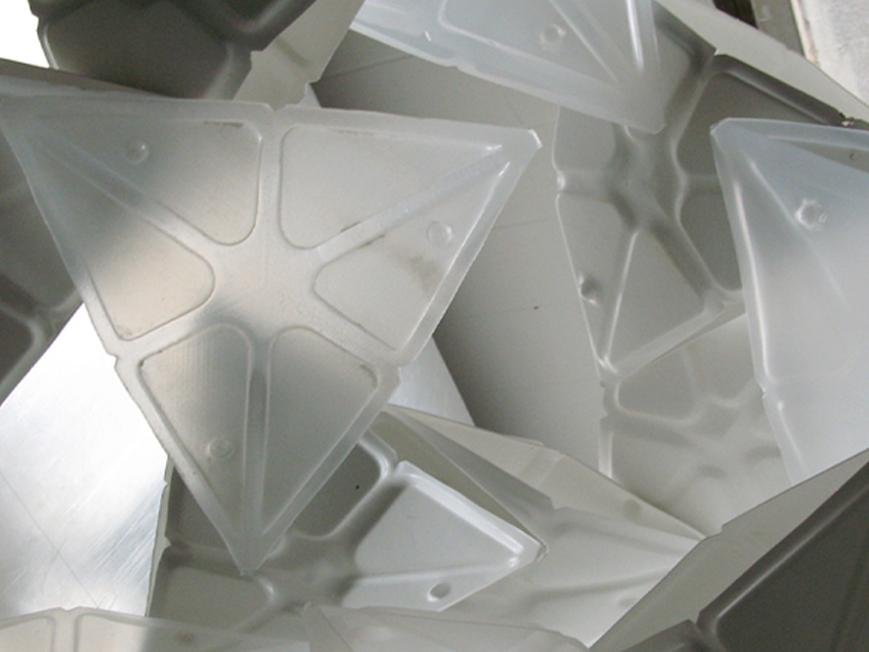
The final mock-up shows a combination of Hard sponged PVC 1mm thick sheets and Polypropylene 0.8mm boards. Each part cosists of two vacuumed prints.¬Ý We designed a set of ribs to ensure rigidness of the whole structure. The proposed connection is a stud-press joint vacummed six times withing each component. Each element has 3planes set at an angle to each other. This allows various assembly positions and unpredictability within the process of mounting.
Considering more efficient wholesale material purchase ‚Äì each element would cost 1 or 2 Fr.¬Ý The wall¬Ý structure¬Ý can be used as room dividers, acoustic diffusors, a toy or mabye somehting completely different ‚Äì something that only the future user can define.
The following issues can be further investigated: scale, material and element thickness, shape „closing” possibilities, optimal drawing of the ribs, connector location and its influence on the whole structure.
.
Jesper Th√∏ger Christensen,¬ÝAleksandar Lalovic,¬ÝNikola Marincic, Mihye An


Given MDF plates, as the main material to use for the construction, physical prototypes made in the workshop were essential to understand the material properties.
Likewise various structural and material tests were necessary to prove the design ideas and methodologies. Programming informed the process and made the final design realisable within the limited time available.
Using the material properties of bending was used to form a network of slightly bent plates, that allows for the forces to travel in a network, without a primary structure having a direct connection to the ground. In other words everything is connected with each other and nothing can be taken out without the structure changing.
Using material properties to guide the development of the design, there was a potential to give each element the desire to be a designer.
Potentially working with the rule of connectivity without defining a limited number of ways of connecting/relating parts to each other.
Meaning the topology is set free in the way that the bent shapes relate to each other. So patterns are not predetermined but come into being as the relations evolve.
Resulting in a pattern with different properties that can be used for different purposes such as controlling structural strength/depth, light transmittance, view etc
Ultimately finding questions instead of giving solution as what the chair has set out to do.
For the proposed design this is however not present, but the potential is still there to be investigated in the future.
In a desire to respond to the conditions of the place a conceptual differentiated shape was discovered.
A simple twist of a cylinder, embracing the two columns of the plan ,turning the inside out and outside in, creating
– an entrance through a covered intermediate space
– an opening to the facade for a view
– while at the same time creating a distinct space closing of to the workplaces around it.
from the approach of the building it creates
– a distinctive gesture that identifies the chair
– and from the staircase it gives approaching students and guests a sensation of something to be discovered.
As the overall shape is a developable surface of a cylinder it is easy to map the curves of the pattern onto the surface. This also allows for the edge of the structure to be controlled in an easy way, and make the connection to the ground straightforward.
For the pattern, various prototypes were made to study the material connections for physical load and in the end a final design that consist of a three layered triangular pattern was constructed.
Plates were not intersecting by crossing, but rather by meeting edge to surface. Resulting in a pattern where a combination of adjoining bent plates and the joint kept each plate into its bent position, creating a network of structural bent plates working together.
This only required 3 small cut outs along the centreline of the plate, not weakening the material as the earlier proposed waffle connections.
The initial idea of a double sided surfaces that turns the inside out and vice versa, was also pursued through the project. After many studies and considerations, a solution that left one side flat and the other more pointy informed the assembly process as well as it distinguished the two sides visually by only changing geometry.
Scripting
A combination of mainly Rhinoscripting with some additional use of Grasshopper have been used continuously through the project.
Grasshopper was mainly used to gain an understanding of the typology of the pattern applied and develop it further.
Whereas Rhinoscripting informed the actual process of assembly in 1:1 by scripting of intersecting plates and distinguishing layers in the structure.
In the final stages Rhinoscripting was also used to automate the preparation of drawings for the Kuka robot and naming each element for ease of assembly
Steps in Rhino
- Twisting cylinder and giving it a thickness as two surfaces
- Generating 2d pattern with 3 layers in grasshopper
- Mapping 2d pattern to twisted cylinder by “flow along surface”
- Lofting lines on two surfaces in Rhinoscripting
- Orienting the planar joints onto the surface with Rhinoscripting
- Using 3 layers to cut plates according to planar joints with Rhinoscripting
- Unrolling bent plates column by column and naming them for final assembly with Rhinoscripting
- Creating cutting paths for 6 mm drill
- Exporting to machine code through Rhinoscripting